ATmega16 Timer0 Phase Correct PWM mit Interrupts
Sourcecode Beispiel um auf dem ATmega16 den Timer0 im Phase Correct PWM mode mit Interrupts zu betreiben.
|
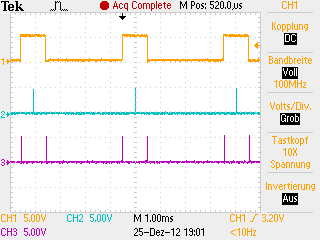
Beschreibung Der Timer 0 wird im Phase correct PWM Modus betrieben. An PB3 wird das PWM Signal ausgegeben. Die Overflow- und Compare Interrupts sind in diesem Programm eingeschaltet und ihr Auftreten wird auf den Digitalkanälen PA0 und PA1 sichtbar gemacht. Jedes mal wenn einer dieser Interrupts stattfindet, erscheint auf seiner PA Leitung ein Puls. Um das PWM signal hochfrequent auszugeben wird der Clockprescaler nicht verwendet. Das PWM Signal wird auf einen Dutycycle von 25% eingestellt. |
Please visit: the four |
C Sourcecode
#include <avr/io.h>
#include <avr/interrupt.h>
int main(void)
{
DDRB = 0x08; // Setup PB3 as output
DDRA = 0x03; // Setup PA0 and PA1 as output
OCR0 = 63; // Set Dutycycle to 25%
TCCR0 |= (1<<WGM00)|(1<<COM01) // Start timer0 without clock prescaler 8
|(1<<CS01)|(1<<COM00); // in non inverting phase correct PWM mode
TIMSK |= (1<<TOIE0) | (1<<OCIE0); // Enable Timer 0 Overflow interrupt
sei(); // Set the I-bit in SREG
for(;;); // Endless loop
// main() will never be left
return 0; // This line will never be executed
}
// Interrupt subroutine timer 0 overflow
ISR(TIMER0_OVF_vect)
{
PORTA ^= 0x01; // Toggle PA0
PORTA ^= 0x01; // Toggle PA0
}
// Interrupt subroutine timer 0 compare match
ISR(TIMER0_COMP_vect)
{
PORTA ^= 0x02; // Toggle PA1
PORTA ^= 0x02; // Toggle PA1
}
Download C-Sourcefile mit ASCII-Schema: C-Sourcefile mit ACII-Schema
Signalplot
|
Gelb: Rechteck Signal an PB3
|


